Introduction
When cooling water flow drops on a PVC pipe extrusion line, the first useful question is where the drop appears. A weak spray pattern in one tank points to a different part of the circuit from a flow drop that affects several lines at once. The location and timing of the change give the production team a starting point before anyone adjusts the machine.
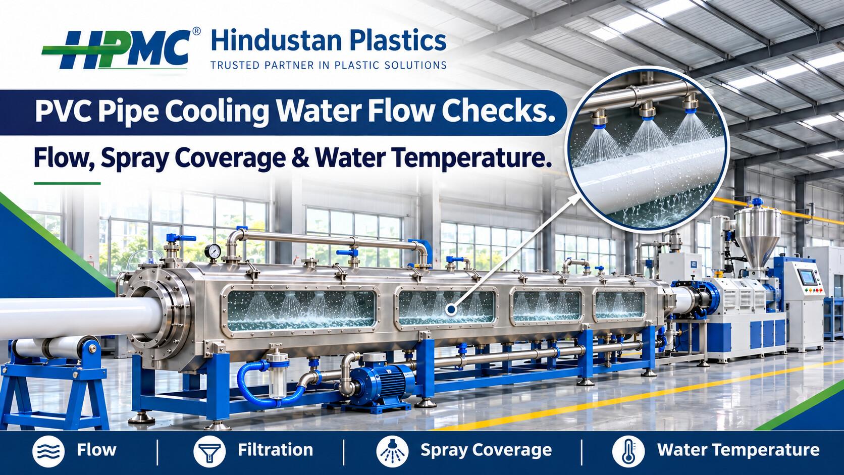
PVC pipe cooling water flow checks cover the supply, sizing sleeve, cooling tanks and return circuit. This guide shows how to compare readings, recognise common patterns and verify whether a change in cooling conditions affected finished pipe quality.
What Does Cooling Water Do in PVC Pipe Extrusion?
The sizing section helps establish the outside diameter as the warm pipe passes through its calibration tooling. Downstream cooling tanks continue removing heat before the pipe reaches the cutter or other handling equipment. A particular line may use spray cooling, immersion cooling or a combination. Check the installed arrangement and identify which sections are in use for the product you are running.
Trace the supply from its source through the pump and filters. Locate any heat exchanger, branch connections and separate feeds to the sizing sleeve. Then follow the return path from each tank. A short circuit sketch with labelled measurement points helps operators and maintenance staff describe the same location when they compare readings.
For the complete equipment sequence, see the PVC Pipe Extrusion Line Guide.
How to Record Cooling Water Flow Consistently
A baseline is a record from a stable run that produced pipe within the required inspection limits. Keep separate records for regularly produced pipe sizes and wall thicknesses. Two products with the same outside diameter can carry different amounts of heat per metre. They may also run at different speeds or use different cooling sections.
Record these details while collecting the reference sample.
- Product setup. Note the outside diameter, wall thickness, sizing sleeve and active cooling sections.
- Production conditions. Record the actual line speed, sample time and output where it is available.
- Water conditions. Record supply and return temperatures, main flow and individual branch flow where meters are installed.
- Tank and filter readings. Note the reservoir level and any available pressure readings before and after the filter.
- Inspection results. Record the sample location, the cooling or conditioning period and the dimensions required by the quality procedure.
Check the Supply and Recirculation Pump
Compare Flow Under Normal Production Conditions
Record main flow once the cooling circuit and production line have settled. Note the measurement unit and which branches are active. Compare the reading with the baseline for the same product and a similar speed. A change that is expected after a product changeover can deserve investigation if it occurs halfway through a stable run.
If flow drops across several lines at the same time, check what they share. Record which other machines started and when the drop appeared. If only one line is affected, trace the supply and recirculation circuit for that line. Include the duration of the change and whether the reading recovers on its own.
Observe Reservoir Level During the Run
A reservoir level that falls can indicate that water is leaving faster than it returns or is replenished. Compare the reservoir level with the level in the cooling tank. If the tank gains water while the reservoir loses it, review the return path and the timing of the change.
Take more than one reading if the problem repeats during the shift. A single observation after the level has recovered may hide an interruption that happens during startup or when another circuit begins drawing water.
Inspect Filters and Read Pressure at the Right Location
Where gauges are installed before and after a filter, read both under comparable operating conditions. The difference is the pressure drop across the filter. A rise from the clean-filter baseline can indicate a restriction. Compare the reading with the equipment supplier’s service criteria and use the plant’s approved maintenance procedure for inspection or cleaning.
After servicing, check whether the pressure drop and the affected flow have recovered. If filter readings improve while one branch remains weak, trace that branch through its valve, hose and manifold. Record the gauge location as well as the reading. Normal pressure close to the pump can coexist with poor delivery farther downstream.
Verify Spray Coverage Around the Pipe
Compare the Active Spray Sections
Through approved viewing points, observe whether the spray reaches the intended areas along the pipe. Identify weak sections or missing spray patterns by tank and manifold position. Where branch flow meters are fitted, compare their readings with the product baseline. Total flow can look normal while an individual section delivers less water than expected.
Compare the affected section with its usual pattern, especially if different spray banks are configured for different products. If a manifold is serviced, observe its coverage again after the line returns to stable conditions. Check a finished sample from the same run to see whether pipe quality changed.
Repeat the Check After a Diameter Change
A different pipe diameter changes where the surface sits relative to the spray outlets. Confirm that the guides and supports keep the pipe in its intended position. Then check coverage for the new product setup. On a dual output line, compare both pipe paths. A difference confined to one strand gives the team a specific area to investigate.
See HPMC’s PVC Conduit Pipe Plant Guide for context on conduit line configurations.
Review Immersion Level and Return Flow
For immersion cooling, use the tank’s recommended operating arrangement for the product. Verify the water level and the position of the pipe relative to the water. Changes in level or pipe position can change the amount of surface exposed to water, even when the supply appears steady.
When the tank level rises or falls, compare the supply reading, tank level and reservoir level at about the same time. Check whether one tank changes or several sections move together. This can help distinguish a local return issue from a change in the shared circuit.
Review recent changes to hoses, valves or drain connections if the issue started after maintenance. Compare the current layout with the documented route. When writing a fault report, record whether the level rises gradually, fluctuates repeatedly or changes only at startup. These patterns give maintenance a better starting point than a single level reading.
Compare Water Temperatures and Line Speed
Track Supply and Return Temperatures
Read the supply temperature at the same location during the run. If it rises while flow and line speed remain close to baseline, review how the water is cooled before it returns to the tanks. On a shared system, note the number of lines running and the time each one came online.
Take supply and return readings close together. Their difference gives context about the heat picked up by the water. Interpret it with the flow rate and production conditions because the quantity of circulating water also affects how much heat the circuit carries away.
Estimate Time in the Cooling Section
Divide active cooling length by line speed to estimate residence time. A pipe moving at 3 metres per minute takes about two minutes to pass through a 6-metre active cooling section. At 6 metres per minute, it takes about one minute.
This comparison helps when a defect starts after a speed increase. Check which cooling sections were active and whether the water conditions changed. Compare finished samples taken at the old and new speeds using the same inspection procedure. The residence time calculation describes how long the pipe stays in the cooling section. Product dimensions, water delivery and temperature also affect the result.
Check the Vacuum Sizing Section Separately
The sizing sleeve and the downstream tank act on the pipe at different stages. If the sleeve has a dedicated water feed, review that branch separately. Compare its condition with the baseline for the installed tooling and pipe size. The downstream tank may operate normally during a change in sleeve water delivery.
Record the vacuum reading alongside the sizing water observations. In an external vacuum sizing arrangement, the pressure difference helps hold the warm pipe against the calibration tool. Check whether the timing of a sizing change matches the first sample that showed dimensional variation.
If sizing and cooling readings remain steady, review upstream production conditions and haul-off speed. HPMC’s Twin Screw Extruder provides context on the upstream equipment used in PVC extrusion.
Match Water Readings With Finished Pipe Quality
Collect samples at agreed intervals and label each one with its time, product and line speed. Follow the same inspection procedure when measuring outside diameter, wall thickness or ovality. For ovality, use the measurement positions specified by the product procedure. Record the cooling or conditioning time before inspection so that the results are comparable.
If a defect repeats on one side of the pipe, record its position and compare it with the pipe path, supports and spray coverage. If variation begins across the output at a specific time, check the log for changes in water conditions, vacuum, speed or material output. Confirm the suspected cause through a repeatable observation.
After an approved adjustment, record the new water readings and check the next sample from stable production. If the flow returns to baseline and the defect continues, document both results and review the other production conditions. HPMC’s guide to Common PVC Pipe Extrusion Defects and Their Causes covers related checks.
Pattern 1. Flow Drops Across Several Tanks
Start with the shared supply and compare the reservoir level, filter readings and active circuits with the baseline. Record whether the issue coincides with another machine starting. If one tank is affected, focus on the supply and return paths specific to that tank.
Pattern 2. Spray Weakens in One Section
Compare the affected manifold with its usual pattern. Review the branch valve position and service history, then ask maintenance to inspect the relevant section using the approved procedure. Confirm coverage and inspect a finished sample after service.
Pattern 3. Water Temperature Rises While Flow Stays Steady
Check whether the cooling supply can maintain its usual temperature at the current production load. Compare the tank inlet reading early in the shift and during peak demand. Record whether the temperature recovers when other equipment stops drawing from the circuit.
Check Whether the Pattern Follows a Changeover
Confirm the correct sizing sleeve, pipe supports and active cooling sections for the new product. Compare the sleeve water feed and line speed with the setup record. Inspect a cooled sample after conditions stabilise, then record the first sample that meets the specification.
How to Build a Useful Production Record
Keep the checklist short enough to complete at the line and detailed enough for the next shift to repeat the readings.
- Before production. Confirm the product, installed tooling and cooling sections required for the run.
- During stable operation. Record flow, water temperatures, reservoir level and filter readings where available.
- At the tanks. Observe spray coverage or immersion level through the approved inspection points.
- At sample collection. Record the time, line speed and vacuum where applicable.
- After an adjustment. Note what changed and compare the next readings and sample with the baseline.
If a problem is unresolved at handover, identify the affected tank and the last acceptable sample. Include the operating conditions under which the issue appears. For example, a branch that loses flow only at peak demand may look normal during a quiet shift. Recording when the issue occurs gives the next operator a better chance of reproducing it.
How to Verify That a Correction Worked
Document the Conditions Before the Work
When a recurring problem is reported, collect readings while it is present if normal operating procedures allow. Record the product, speed and approximate time since startup. Include the active cooling sections and the equipment sharing the water supply. These details let the team repeat the conditions after maintenance and avoid comparing a fully loaded system with a quiet one.
Keep a record of the part or section serviced. For example, if a technician cleans the manifold at the outlet end of the second tank, identify it by name or position. A clear service record helps the operator check the same section when the line returns to production.
Use the Same Inspection Points After Restart
Wait for the production and water readings to settle before collecting comparison samples. Use the same flow meter, temperature points and inspection method as before. If the problem usually appears late in the shift, repeat the checks at that time. A short run immediately after restart can confirm that the equipment operates, while the later check shows how it behaves under the conditions that triggered the complaint.
Record the outcome in the production log and note when the team should repeat the check.
What to Share When Requesting Technical Support
Share the pipe dimensions, line speed and cooling tank layout. Include a set of flow and temperature readings from a good run and from the run when the issue appeared. Mark the measurement points so the two sets of readings can be compared.
Describe whether the problem affects one spray bank, an entire tank or several lines. Mention any tooling change or cooling circuit work. Add the time of the last acceptable sample and the first sample that showed variation. This gives the equipment team a picture of where to begin the review.
Conclusion
PVC pipe cooling water flow checks are most useful when operators trace the circuit and connect their readings to finished pipe measurements. Establish a baseline for each product, compare flow and temperature during stable operation and review individual branches when a problem affects only part of the line. Verify the effect of each adjustment on the next sample.
Contact HPMC
HPMC (Hindustan Plastics and Machinery Corporation).
For an equipment review, share your pipe size, line speed, cooling tank layout and recent water readings. HPMC Technical Assistance.
Address: 5, Category II, DSIDC Industrial Area, Nangloi, Delhi – 110041, India.
Website: www.hindustanplastics.com.
Phone: +91 95605 96392.
Email: info@hindustanplastics.com.
Frequently Asked Questions
Find quick answers to the most common questions about this topic.
They help determine whether the sizing and cooling sections receive water consistently. Pair the readings with finished pipe measurements to see whether the conditions changed when the defect appeared.
Use the supplier’s guidance for the tank, pipe size and line conditions. Record a baseline from a stable run that meets the product specification.
Yes. A branch restriction can reduce local water delivery while the pump continues running. Check the affected branch and compare it with its baseline.
Where gauges are fitted, compare the pressure before and after the filter under similar operating conditions. Use the clean-filter baseline and supplier’s service criteria.
A different diameter changes the distance from the pipe surface to the spray outlets. Verify coverage and pipe support for the new setup.
The cooling system may be serving more equipment or may be losing capacity. Compare the supply temperature with the number of operating lines and production conditions.
It reduces the time the pipe spends in the same active cooling length. Check water conditions and finished dimensions at the higher speed.
Yes. Compare spray coverage, pipe supports and sizing conditions, then assess cooled samples using the same inspection method.
Compare supply flow, tank level and reservoir level. If the change is confined to one tank, review its return path and level control using the equipment procedure.
Follow the plant’s inspection schedule. Repeat the checks after a product change, significant speed change, cooling circuit service or unexplained dimensional variation.