
Introduction
Electrical wires and cables require insulation and protective layers that meet the specifications of their intended application. During manufacturing, these layers must be applied consistently to support dimensional accuracy, surface quality and reliable cable construction.
A two-layer cable extrusion line applies two polymer layers during a continuous production process. Depending on the cable design, these layers may serve different functions, such as electrical insulation and an outer protective sheath. For machine details and available configurations, see HPMC’s High Speed Two Layer Cable Plant product page.
For cable manufacturers, selecting suitable extrusion equipment is only one part of the process. Material compatibility, crosshead design, temperature control, line synchronization and routine quality checks also influence the finished cable.
What Is a Two-Layer Cable Extrusion Line?
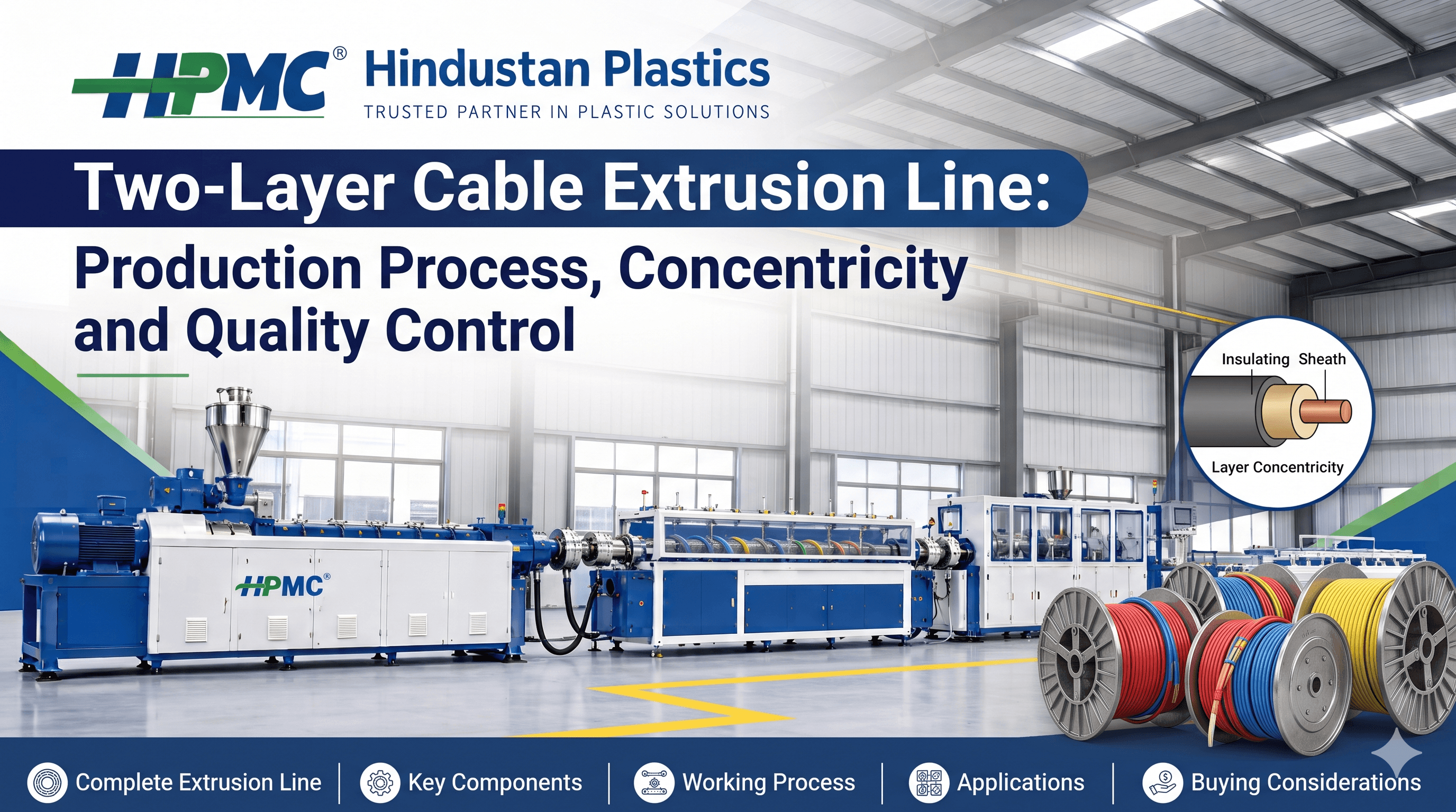
A two-layer cable extrusion line is a manufacturing system that applies two polymer layers around a wire or cable conductor in one continuous production process. In a typical configuration, the conductor passes through a crosshead and die arrangement designed to distribute the selected polymer materials around it. The line then uses appropriate cooling, pulling and take-up equipment to handle the coated cable.
Depending on the cable design, the two layers may consist of different materials or formulations. The exact configuration depends on conductor size, cable construction, material combination, finished diameter and applicable product specifications.
How Does a Two-Layer Cable Extrusion Line Work?
A typical production sequence includes the following stages. The actual arrangement can vary according to the machine configuration and cable application.
1. Conductor Pay-Off
The conductor is supplied from a suitable reel or pay-off arrangement. Stable conductor feeding helps maintain a consistent path through the extrusion crosshead.
2. Material Feeding and Preparation
The selected polymer materials are supplied to their respective extruders. Material preparation requirements depend on the polymer grade, formulation and supplier instructions.
3. Melting and Extrusion
The extruders convey and process the polymer materials under controlled operating conditions. Screw design, material properties, temperature settings and output requirements influence processing behaviour.
4. Two-Layer Crosshead and Die
The crosshead brings the processed materials together around the conductor. The die arrangement forms the required layer structure and cable dimensions. Correct tooling selection and setup are important for maintaining the intended layer thickness and distribution.
5. Cooling
After leaving the die, the coated cable passes through a suitable cooling arrangement. Cooling conditions should support the required shape and surface finish without disrupting the production process.
6. Diameter Measurement and Inspection
The cable is checked against the required dimensions and construction specifications. Depending on the production setup, inspection may include outside diameter, surface appearance, layer thickness, concentricity and other application-specific properties.
7. Capstan or Caterpillar Pulling
The pulling system moves the cable through the line at a controlled speed. Its operation must be coordinated with extrusion output to help maintain consistent coating dimensions.
8. Take-Up and Final Checks
The finished cable is collected using a suitable take-up system. Winding tension and handling should be appropriate for the cable construction to avoid unnecessary deformation or damage.
Why Layer Concentricity Matters
Concentricity describes how evenly the insulation or sheath is distributed around the conductor or underlying cable layer. Inconsistent layer distribution can cause one side of the cable coating to become thinner than intended. Acceptable variation depends on the cable design and applicable specifications.
Factors that can influence concentricity include conductor alignment, die installation, material flow, stable conductor and line speed, extrusion output and consistent material properties. Manufacturers should use suitable inspection methods to verify the finished cable rather than relying only on its external appearance.
Temperature Control in Two-Layer Cable Extrusion
Temperature control is important because each polymer has its own processing requirements. Extruder zones, crosshead and die temperatures, and cooling conditions should be appropriate for the selected materials and production rate.
Record relevant temperature settings and actual readings during production. Consistent records help operators compare batches and investigate recurring issues. Temperature should not be changed without considering material condition, output, die setup and line speed.
Material Selection for Two-Layer Cable Manufacturing
Material selection depends on the electrical, mechanical, environmental and dimensional requirements of the finished cable.
PVC
PVC compounds are used in various wire and cable applications. Their suitability depends on the formulation and the cable's intended requirements. For more context on processing PVC compounds, read HPMC’s Single Screw Extruder for PVC Compounding article.
Polyethylene
PE grades may be used in suitable insulation or sheathing applications. The selected grade should match the cable design and processing conditions.
XLPE and Other Cable Materials
XLPE and other cable materials may require specific processing arrangements and production controls. Their suitability for a particular two-layer line must be confirmed against the machine configuration and material requirements.
Not every extrusion line can process every cable material or material combination. Confirm compatibility with the machinery supplier and material supplier before production.
Common Two-Layer Cable Extrusion Problems
1. Uneven Outer Diameter
Possible causes include inconsistent extrusion output, changes in pulling speed, unsuitable die conditions or variations in material properties. Review diameter measurements, output records, pulling speed and tooling setup.
2. Uneven Layer Thickness
Uneven layer thickness may be associated with conductor alignment, die setup, material flow or unstable line operation. Inspect the cable using an appropriate method for evaluating layer distribution.
3. Rough Surface Finish
Surface defects may be related to material contamination, unsuitable processing conditions, deposits around the die or other process variations. Record when the defect appears and inspect material quality, process readings and tooling condition.
4. Inconsistent Production Speed
Changes in line speed or synchronization between extrusion and pulling equipment may affect cable dimensions and surface consistency. Compare line-speed records with extrusion output and dimensional measurements.
5. Material Flow Instability
Unstable material feeding or variations in processing conditions may affect the flow of one or both layers. Review material batches, feeding conditions, temperature records and relevant machine readings.
Quality Control Checklist for Two-Layer Cable Production
A documented inspection routine can help manufacturers verify that production remains within the required specifications.
Quality checkWhat to verify
Material identification
Correct polymer grade and batch
Conductor condition
Surface condition and consistent feeding
Outside diameter
Compliance with required dimensions
Layer thickness
Appropriate distribution of each layer
Concentricity
Layer distribution around the conductor
Surface finish
No unacceptable visible defects
Line synchronization
Stable relationship between output and pulling speed
Process records
Relevant settings, readings and inspection results
Final product
Compliance with the applicable cable specification
Inspection methods and acceptance limits must be based on the cable design, applicable standards and the manufacturer's quality procedures. Visual inspection alone cannot confirm every electrical or mechanical property.
How to Select a High-Speed Two-Layer Cable Plant
Choosing a cable extrusion line should begin with the finished product requirements rather than maximum line speed alone.
1. Define Cable Specifications
Identify conductor dimensions, finished cable diameter, layer structure, material grades and the required production range.
2. Confirm Material Compatibility
Ask the machinery supplier to confirm that the proposed extruders, crosshead and die arrangement are suitable for the intended materials.
3. Evaluate Extruder Configuration
Review available extruder models, screw design, drive configuration and stated output specifications. When comparing extrusion technologies, HPMC’s Twin Screw Extruder vs Single Screw Extruder article may help explain general differences, although cable-line suitability must be confirmed for the specific machine.
4. Check Crosshead and Die Options
Confirm that the crosshead arrangement and tooling can produce the intended two-layer construction and required dimensions.
5. Review the Pulling System
Check the suitable cable diameter range, traction arrangement and speed requirements. The pulling system should be matched to the intended production conditions.
6. Evaluate Temperature and Process Controls
Review the temperature-control arrangement and available monitoring features. Confirm which operating parameters can be monitored and adjusted on the selected configuration.
7. Assess the Complete Line
Consider conductor pay-off, extrusion, crosshead, cooling, diameter inspection, pulling and take-up as parts of one coordinated production system.
8. Discuss Service and Installation
Before purchasing, clarify installation requirements, commissioning, operator training, spare parts and technical support. For machine-specific options and available configurations, refer to HPMC’s High Speed Two Layer Cable Plant product page.
Why Consider HPMC for Cable Extrusion Machinery?
Hindustan Plastics and Machinery Corporation (HPMC) manufactures extrusion and plastic-processing machinery for different industrial applications. Its High Speed Two Layer Cable Plant product page provides information about the machine configuration, crosshead options, two-layer die head, capstan and available model specifications.
Manufacturers considering this equipment should discuss their cable construction, conductor size, material combination, required output and finished-product specifications with the supplier. Machine selection should be based on confirmed specifications and production requirements rather than general claims about speed or efficiency.
Contact HPMC
HPMC (Hindustan Plastics & Machinery Corporation)
Address: 5, Category II, DSIDC Industrial Area, Nangloi, Delhi – 110041, India
Website: https://www.hindustanplastics.com/
Phone: +91 95605 96392
Email: info@hindustanplastics.com
Google Business Profile: https://share.google/lBK4uD53HqY891ynv
Frequently Asked Questions
Find quick answers to the most common questions about this topic.
It is a production system designed to apply two polymer layers around a conductor or cable in a continuous extrusion process.
The layers may perform different functions, such as insulation and outer protection. Their precise purpose depends on the cable design and applicable specifications.
Materials may include suitable PVC, PE, XLPE and other cable-grade compounds, depending on the machine configuration and cable requirements. Compatibility should be confirmed before production.
The crosshead guides the processed polymer materials around the conductor and helps form the required layer structure through the die arrangement.
Concentricity indicates how evenly a layer is distributed around the conductor or underlying layer. The required tolerance depends on the finished cable specification.
Possible causes include conductor misalignment, die setup, inconsistent material flow, process variation and unstable line speed.
Temperature influences polymer processing and material flow. Settings must be appropriate for the selected material, machine configuration and production conditions.
Their relationship affects the amount of material deposited along the cable. Instability may contribute to dimensional or coating variation.
That depends on the extruder design, material compatibility, tooling and required cable construction. Confirm the supported combinations with the machinery supplier.
Evaluate cable dimensions, layer requirements, material compatibility, extruder configuration, crosshead and die options, pulling system, controls, installation and technical support.